Renishaw PH10 Installation Guide
Browse online or download Installation Guide for Recording Equipment Renishaw PH10. Renishaw PH10 Installation guide User Manual
- Page / 74
- Table of contents
- TROUBLESHOOTING
- BOOKMARKS
- EXTENDED WARRANTY 1
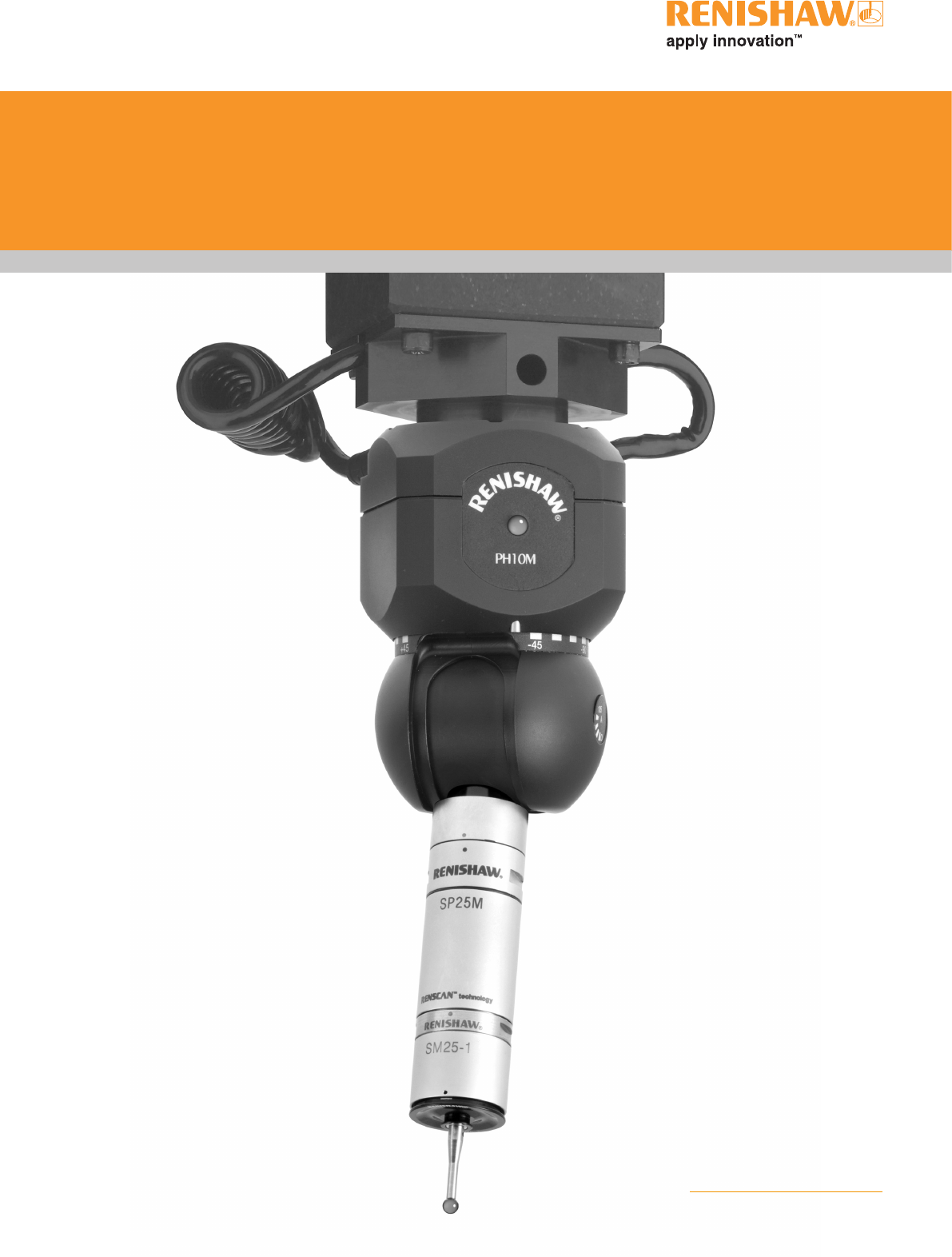
- PH10 series 3
- Contents 5
- FCC and TÜV 7
- EC DECLARATION OF CONFORMITY 8
- EN - Warnings 9
- Electrical requirements 12
- Fuse replacement 12
- Environmental requirements 12
- 1 Introduction 13
- 2 System description 14
- System description 15
- 2.3 PH10 system layout 17
- 3 Installation 21
- Installation 22
- RS232 serial communications 27
- 4.1 RS232 connector pinouts 28
- 4.2 Baud rate selection 28
- 4.3 Protocol selection 28
- IEEE parallel communications 31
- 5.1 IEEE connector pinouts 32
- 5.2 IEEE488 capability 32
- 5.3 Protocol selection 33
- 6.2 Interface connection 34
- 6.3 HCU1 operation 35
- 6.4 Output configuration 35
- 6.5 Probe reset time 37
- 7 PHC10-2 front panel LEDS 41
- 8 PICS stop signal 42
- 9 Accessories 43
- 9.2 AM1 adjustment module 44
- 9.3 AM2 adjustment module 45
- 11 Troubleshooting 51
- BG - Предупреждения 52
- CS - UPOZORNĚNÍ 53
- DA - SIKKEREDHED 54
- DE - SICHERHEITSANWEISUNGEN 55
- EL - ΑΣΦΑΛΕΙΑ 56
- ES - SEGURIDAD 57
- ET - HOIATUSED 58
- FI - TURVALLISUUTTA 59
- FR - SECURITE 60
- Éire - Foláirimh 61
- HU - FIGYELMEZTETÉS 62
- IT - SICUREZZA 63
- LT - ĮSPĖJIMAI 64
- LV - BRĪDINĀJUMS 65
- MT - TWISSIJIET 66
- NL - VELIGHEID 67
- PL - BEZPIECZEŃSTWO 68
- PT - SEGURANÇA 69
- RO - ATENŢIE 70
- SK - VÝSTRAHY 71
- SL - OPOZORILA 72
- SV - SÄKERHETSFÖRESKRIFTER 73
- *H-1000-5071-09* 74
Summary of Contents
Installation guide H-1000-5071-09-APH10 motorised heads and controllersEXTENDED WARRANTYNow available for this product.Contact your vendor. www.renish
viiiSafetyInternational safety instructionsEN WARNING: Please turn to appendix 1 and read the safety instructions in your own language before unpack
ixNL VELIGHEID: Ga nu naar Appendix 1 en lees de veiligheidsinstructies, in uw eigen taal, voordat u dit product uitpakt en installeert.PL BEZPIECZ
xSafetySafety Electrical requirementsThe PHC10-2 is powered from the a.c. mains supply via an IEC 320 connector. The operating voltages of the unit ar
1Introduction1 IntroductionThis guide describes the installation of the PH10 series of motorised probe heads and the PHC10-2 probe head controller.Th
2System description2 System description2.1 PH10 series motorised probe headsEach of the heads in the PH10 motorised probe head range is a general pu
3System descriptionFigure 2 - PH10M with AM1 and TP7MB axisA axisB axisA axisFigure 2 shows the shank-mounted PH10M motorised probe head fitted with an
4System description2.2 PHC10-2 probe head controllerThe PH10 series of motorised probe heads can only be used in conjunction with the PHC10-2 control
5System description2.3 PH10 system layoutFigure 5 shows the PH10T/PH10M and PHC10-2 used in conjunction with two-wire touch-trigger probes and approp
6System description2.4 Probes, extensions and styliFigure 7 shows the range of extensions, probes and styli which can be used in conjunction with the
7System descriptionFigure 8 shows the range of extensions, probes and styli which can be used in conjunction with the PH10M and PH10MQ heads.Figure 8
© 1988 - 2008 Renishaw plc. All rights reserved. This document may not be copied or reproduced in whole or in part, or transferred to any other media
8System descriptionThe maximum cable length for the PH10 system is 50 m, on condition that the maximum single wire resistance is less than 2.5 W.The m
9Installation3 Installation3.1 Installation and dimensions of PH10 series headsFigure 9 shows the dimensions of the shank-mounted PH10T head.Figure
10Installation!Figure 10 - Dimensions of PH10M CAUTION: Always fit mounting shanks with the screws supplied (M3 x 5 mm long). The use of incorrect
11Figure 11 - Dimensions of PH10MQ80 mm (3.15 in) squareA axis 105°B axis60 mm (2.36 in)39 mm (1.54 in) (to rollers)Multiwire connector73 mm (2.87 in)
12Installation3.2 Installation of PHC10-2 controllerBoth versions of the PHC10-2 controller can be used in a 19” rack system or as a stand-alone unit
13InstallationFigure 13 - Fitting blanking panel and rack mounting bracketThe rack mounting bracket kit (1) is part number A-1018-0124. The blanking
14Remove the blanking plugs from the side panels of the PHC10-2. Fit a rack mounting bracket (1) and an enclosure link bracket kit (3) using the screw
15RS232 serial communications4 RS232 serial communicationsFigure 16 shows the rear panel of the RS232 version of the PHC10-2.12 43 5 6 7 8 91011 12Fi
16RS232 serial communications4.1 RS232 connector pinoutsThe PHC10-2 communicates with the CMM computer via the RS232 cable as shown in table 1.Table
17RS232 serial communications4.3.1 Basic command set modeIn this mode the PHC10-2 is fully compatible with existing integration methods in terms of
PH10 seriesInstallation guide
18RS232 serial communicationsThe extended command set offers the following advantages over the basic command set:• Software control of the hand contr
19IEEE parallel communications5 IEEE parallel communicationsFigure 17 shows the rear panel of the PHC10-2 IEEE.12 43 5 6 7 8 91011 12Figure 17 - PHC1
20IEEE parallel communications5.1 IEEE connector pinoutsThe PHC10-2 IEEE488 connector is compatible with any standard IEEE488 cable. The pin numbers
21IEEE parallel communications5.3 Protocol selectionThe IEEE488 device address is selected via switches 1 to 5 using binary code (see table 6). The r
22Probing system output (RS232 and IEEE)6 Probing system output (RS232 and IEEE)Both versions of the PHC10-2 have a further eight configuration switch
23Probing system output (RS232 and IEEE)6.3 HCU1 operationWhen the system is used in conjunction with an HCU1 hand control unit (see section 9.1), th
24Probing system output (RS232 and IEEE)Table 11 - PICS connector pinoutsPin Signal Position1 STOPThis signal is active when low and is responded to,
25Probing system output (RS232 and IEEE)6.4.2 SSR outputThe pin numbers and descriptions are given in table 12.Table 12 - SSR connector pinoutsPin De
26Probing system output (RS232 and IEEE)Table 14 - Head connector cablesMachine cable Probe head cableSignal name15-way male D-type connectionsCable P
27Probing system output (RS232 and IEEE)6.7 Summary of configuration switches6.7.1 Summary of RS232 configuration switchesTable 16 presents a summary
This page was intentionally left blank.
28Probing system output (RS232 and IEEE)6.7.2 Summary of IEEE configuration switchesTable 17 presents a summary of the PHC10-2 IEEE configuration switc
29PHC10-2 front panel LEDs7 PHC10-2 front panel LEDSFigure 18 shows the front panel of the PHC10-2. The names, colours and functions of the LEDs are
30PICS stop signal8 PICS stop signalThe PHC10-2 will assert STOP under the following conditions (table 19):Table 19 - PHC10-2 LEDsCondition NotesOver
31Accessories9 Accessories9.1 HCU1 hand control unitThe HCU1 is a remote hand control unit which enables the head to be used in manual mode or with
32AccessoriesYawOvertravelPitchRollAM1Lock / unlock screw9.2 AM1 adjustment moduleThe PH10T and PH10M have been designed to be mounted in any orienta
33Accessories9.3 AM2 adjustment moduleThe PH10MQ has been designed to be mounted directly on your machine quill in any orientation.The AM2 allows fine
34System interconnection diagrams10 System interconnection diagramsThis section describes a number of PH10 system interconnections and recommends inte
35System interconnection diagramsPH10TPH10MPL5, 6, 12, 13PLM6, 7, 8, 9Communication connection to CMM controllerPL25Raw probe signal to OEM interfaceH
36System interconnection diagramsFigure 23 - PH10 system with standard two-wire touch trigger probe and autochangeTable 22 - Switch settingsPICS config
37System interconnection diagramsFigure 24 - PH10 system with multiwired probesTable 23 - Switch settingsPICS configuration SSR configurationUp Down Up
iiiContentsContentsFCC and TÜV ...
38System interconnection diagramsFigure 25 - PH10 system with multiwired probes and autochangeTable 24 - Switch settingsPICS configuration SSR configura
39Troubleshooting11 TroubleshootingThis section on troubleshooting is a guide to problems associated with the installation and integration of the syst
40Предупреждения12 Appendix 1 - International safety statementsBG - ПредупрежденияСъществуват рискове от притискане между движещи се части и между дви
41CS - UPOZORNĚNÍ
42SIKKEREDHEDDA - SIKKEREDHEDDer er risiko for at blive klemt mellem bevægelige dele og mellem bevægelige og statiske dele. Hold ikke sondehovedet und
43SICHERHEITSANWEISUNGENDE - SICHERHEITSANWEISUNGENZwischen beweglichen und zwischen beweglichen und statischen Teilen besteht Einklemmgefahr. Der Dre
44ΑΣΦΑΛΕΙΑEL - ΑΣΦΑΛΕΙΑΥπάρχει κίνδυνος πιασίματος μεταξύ των κινούμενων μερών όπως και μεταξύ των κινούμενων και στατικών μερών. Μη συγκρατείτε την κ
45SEGURIDADES - SEGURIDADExiste el peligro de atraparse los dedos entre las distintas partes móviles y entre partes móviles e inmoviles. No sujetar la
46HOIATUSEDET - HOIATUSEDMasina liikuvad osad võivad põhjustada muljumisohtu. Ärge hoidke masina liikumise ajal või sondi vahetamise ajal kinni sondip
47TURVALLISUUTTAFI - TURVALLISUUTTALiikkuvien osien sekä liikkuvien ja staattisten osien välillä on olemassa puristusvaara. Älä pidä kiinni anturin pä
iv6.5 Probe reset time ...256.6 He
48SECURITEFR - SECURITEL’effet de pincement dû au mouvement des pièces mobiles entre elles ou avec des pièces fixes présente des dangers. Ne pas tenir
49FoláirimhÉire - FoláirimhTá guaiseacha cúngúcháin ann idir páirteanna atá ag gluaiseacht agus idir páirteanna atá ag gluaiseacht agus páirteanna sta
50HU - FIGYELMEZTETÉS
51SICUREZZAIT - SICUREZZAEsiste pericolo di danno da schiacciamento tra le parti in moto o tra le parti in moto e quelle ferme. Evitare di afferrare l
52LT - ĮSPĖJIMAI
53LV - BRĪDINĀJUMS
54MT - TWISSIJIETHemm il-periklu li wieħed jinqaras bejn biċċiet li jiċċaqilqu u bejn biċċiet li jiċċaqilqu u biċċiet statiċi. Iżżommx ir-ras tas-sond
55VELIGHEIDNL - VELIGHEIDEr is risico op inklemming tussen de bewegende onderdelen onderling en tussen bewegende en niet-bewegende onderdelen. Houd de
56PL - BEZPIECZEŃSTWO
57SEGURANÇAPT - SEGURANÇAExiste perigo de esmagamento entre as peças móveis/estáticas do equipamento. Não segurar no cabeçote apalpador durante os mov
vFCC and TÜVFCC (USA)Information to the user (FCC section 15.105)NOTE: This equipment has been tested and found to comply with the limits for a Class
58ATENŢIERO - ATENŢIE
59SK - VÝSTRAHY
60SL - OPOZORILAPazite, da se ne uscipnete med gibajocimi deli ter med gibajocimi in staticnimi deli. Ne drzite glave sonde med premiki ali med rocno
61SV - SÄKERHETSFÖRESKRIFTERDet finns risk för klämning mellan rörliga delar och mellan rörliga och stillastående delar. Håll inte i probhuvudet under
Renishaw plcNew Mills, Wotton-under-Edge, Gloucestershire, GL12 8JR United Kingdom T +44 (0)1453 524524 F +44 (0)1453 524901 E [email protected]
viEC DECLARATION OF CONFORMITYRenishaw plc declare that the product: - Name: PHC10-2 series Description: Probe head controller Part numbers: A-1
viiEN - WarningsPinch hazards exist between moving parts and between moving and static parts. Do not hold the probe head during movements, or when man
More documents for Recording Equipment Renishaw PH10


Related products and manuals for Recording Equipment Renishaw PH10


 (68 pages)

© 2020, manymanuals.com. All rights reserved. | 1.108 s |
 Manymanuals.com
 Manymanuals.de
 Manymanuals.fr
 Manymanuals.it
 Manymanuals.pl
 Manymanuals.cz
 Manymanuals.es
 Manymanuals-pt.com
Comments to this Manuals